|
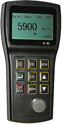
This gauge is a simple to use, high accuracy, hand-held Ultrasonic
Thickness Gauge with the ability to measure through paint and
coatings and even to eliminate the thickness of the paint or
coating. Through-Coating Thickness Measuring Capability
- You can now test painted tanks, pipes, etc.,
without having to remove the paint or make corrections for the paint
thickness.
Ideal for measuring the effects of corrosion or erosion on tanks,
pipes or any structure where access is limited to one side.
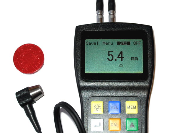
Operating principle:
Standard mode: P-E (pulse-echo) method with dual-element probes
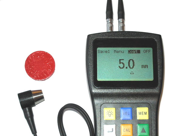
Coating
mode: E-E (echo-echo) method with dual-element probes
|
| |
|
 |
 |
|
SR1911D
Thru-Paint
(Through coating, Through paint)
ultrasonic thickness gauge
Interfaces:
Serial
RS 232C port in combination with a communicative cable;
Data
transfer parameters: 8 bits, 1 stop bit, 9600 baud, no parity.
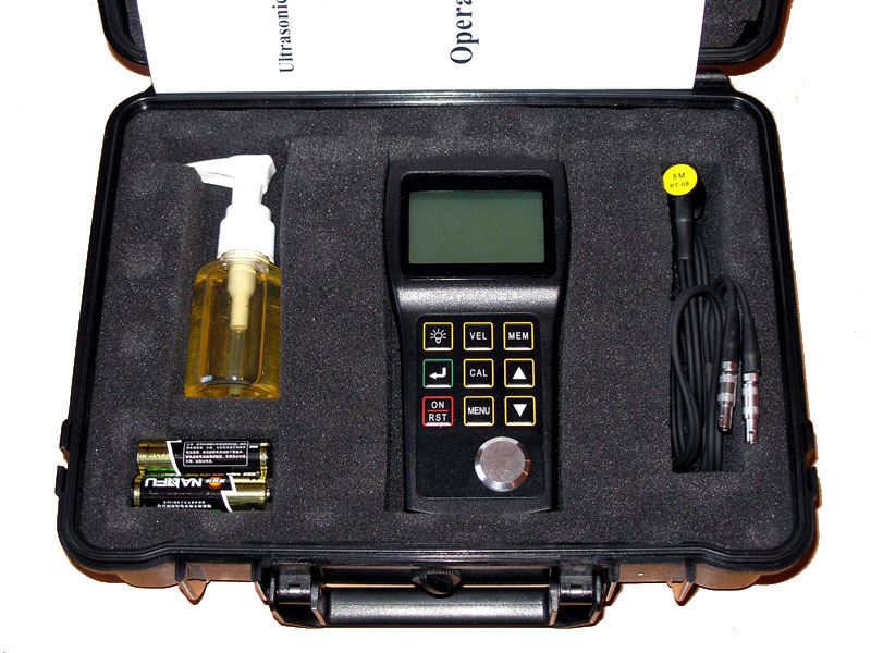
Standard package:
SR8911D
thickness gauge, Standard probe (PT-08)
Carrying case, Two 1.5V AA alkaline batteries
Couplant, Operating manual
Optional accessories:
Attachable rubber case
Numerous special probes on request
Couplants and high-temperature couplant
4-step/6-step block for calibration
Data
transmission cable
Application software |
SR1912D
Thru-Paint (Through
coating, Through paint)
ultrasonic thickness gauge
Interfaces:
Serial
RS 232C port in combination with a communicative cable;
Data
transfer parameters: 8 bits, 1 stop bit, 9600 baud, no parity.
Standard package:
SR8912D
thickness gauge, Standard probe (PT-08)
Carrying case, Two 1.5V AA alkaline batteries
Couplant, Operating manual
Optional accessories:
Attachable rubber case
Numerous special probes on request
Couplants and high-temperature couplant
4-step/6-step block for calibration
Data
transmission cable
Application software |
|
|
Specification |
Model |
SR1911D |
SR1912D |
|
Measuring range |
Metric Imperial |
0.8mm to 300mm; 0.031in to 11.81in in standard mode
3.0mm to 18.0mm; 0.118in to 0.709in in through coating
mode
Depending on probe, material and surface condition |
|
Operating principle |
Ultrasonic |
|
Digital resolution |
0.001in or 0.1mm (less than SR1912D) |
H<4in
: 0.001in /0.01in or 0.01mm/0.1mm;
H≥4in : 0.01in or 0.1mm |
|
Units |
Selectable: inch or mm |
|
Display |
128*64 dot-matrix LCD screen (1.65in*2.24in; 42mm*57mm)
EL backlight and switchable contract ratio |
|
Measurement update rate |
4 Hz in standard measurement mode
25 Hz in MIN capture mode |
|
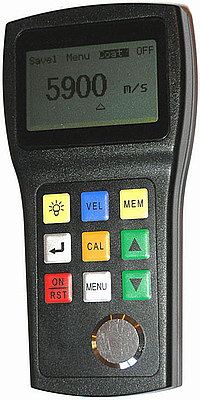
Material velocity range |
1000 to 9999 m/s; 0.039 to 0.394 inch/µs |
|
Power supply |
Two 1.5V AA alkaline batteries |
|
Warning with low battery voltage |
√ |
|
Auto shut-off |
After 5 minutes of non-use |
|
Probe zero adjustment |
Selectable: 1-point calibration: normal measurement
2-point calibration: curve surface
measurement or other special application with a high
precision |
|
V-path correction |
Automatic |
|
Dimensions |
149mm*73mm*32mm (H*W*D) |
|
Whole weight |
200g; 7oz (including batteries) |
|
Packing |
1PCS/CTN, CTN SIZE: 28*24*11, G.W.: 1.5KGS |
|
Display contents |
thickness value, coupling state, power state, CAL
calibration state, sound velocity |
|
Data logger capacity |
Up to 500 readings can be divided into a maximum of 5
files (user-selectable) |
|
Measuring error |
Up to 1in: ±0.002in or ±0.1mm
Above 1in: ± 1%H
H is the height of the testing object |
Up to 1in: ±0.002in or ±0.05mm
Above 1in: ±0.5%H
H is the height of the testing object |
|
Repeatability |
±0.001in or ±0.1mm |
±0.001in or ±0.025mm |
|
Application software |
UMVIEW |
|
Interfaces |
RS232 |
|
| |
|
.jpg)
★Color
320*240 Pixels Display
★A-Scan
Snapshot
★Echo-Echo
Mode(Thru Paint&Coatings)
★Stores
100000 Readings
★Gain:Low,Medium
or High for varying test conditions |
SR1914 Ultrasonic Thickness Gauge
Main functions of SR1914
The only product using
clear bright color OLED in the same product class.
Contrast:10000: 1 40 times than TFT color LCD screen
Resolution320*240,9 times than the same product class
Faster measurement update rate
Selectable 4Hz, 8Hz, 16Hz,4Hz for
ordinary use,higher update rate can be chosed when need a quick
scan.
The innovative A scanning snapshot function
Marks the economical thickness gauge into digital age.
SR1914 first provides A snapshot
scanning waveform display function in the same product
class.Ultrasonic is no longer an abstract concepts.Users can see
directly on the screen of ultrasonic signal,to verify the thickness
reading is correct, analyze the cause of the problem and help the
user to find the solution to the problem.
Industry's first economical digital thickness gauge
The zero measurement technology, high resolution, A scanning
snapshot function is based on full digital technology.
The only real 0.01 mm resolution of
ultrasonicthickness meter in the same product class.
Ultrasonic thickness gauge display resolution is
usually 0.01 mm, but it's hard for the real resolution up to 0.01
mm.Ordinary Timing counter within the thickness gauge is generally
below 30 MHZ,With the breakthrough full digital technology and
special algorithm, The true resolution of SR1914 can reach 0.01 mm,
Lots of experiments prove that it's easy for SR1914 to distinguish
that thickness is only 0.01mm of two blocks.
Adopted the zero measurement technology
Based on full digital technology,with the zero
measurement technology,the measured value will not be affected by
echo intensity,material attenuation coefficient,the gain and the
height of the gate,so the result was of high stability and
reliability.
More practical function
Alarm,DIFF/RR%,Min/max Capture
|
SR1914 Series Technical Specifications
|
Instrument Specifications |
|
Display Type |
2.4" color OLED, 320 * 240 pixels, contrast 10,000:1 |
|
Operating Principle |
Pulse echo with dual element transducers |
|
Measuring Range |
0.60mm to 508mm(0.025" to 20.00"), depending on material,
probe and surface condition |
|
Measuring Resolution |
Selectable 0.01mm, 0.1mm (selectable 0.001",
0.01") |
|
Units |
Inch or Millimeter |
|
Gain |
Low, Medium or High for varying test conditions |
|
Display Mode |
Normal, Minimum / Maximum capture, DIFF/RR% |
|
V-Path Correction |
Automatic |
|
Update Rate |
Selectable 4Hz, 8Hz, 16Hz |
|
Material Velocity Range |
500 to 9999m/s (0.0197 to 0.3937in/us) |
|
Languages |
Selectable Chinese, English, Japanese |
|
Alarm Settings |
Minimum and Maximum alarms. Range of 0.25 mm to 508 mm
(0.010" to 20.00").Dynamic waveform color change on alarm |
|
Power Requirements |
2 AA size batteries |
|
Operating Time |
Approximately 40 hours |
|
Instrument Shut-off |
Selectable ALWAYS ON or AUTO OFF after 5, 10, 20 minutes of
inactivity |
|
Operating Temperature |
-10°C to +50°C (+10°F to +120°F) |
|
Size |
153mm * 76mm * 37mm(H * W * D) |
|
Weight |
280g including batteries |
SR1914 Standard Configuration
|
SR1914 thickness gauge |
1 |
Standard Probe |
1 |
|
Carrying Case |
1 |
Couplant |
1 |
|
Operating Mannual |
1 |
1.5AA Alkaline batteries |
2 |
|
SR1914 Series Probe/Transducer Specifications |
|
Model |
PT08 |
TC510 |
PT12 |
ZT12 |
PT06 |
PT04 |
GT12 |
|
Type |
SR1914 Standard |
SR1914D/SR1914DL Standard |
Standard |
Cast iron |
Small tube |
Fingertip |
High-Temperature |
|
Frequency |
5MHz |
5MHz |
5MHz |
2MHz |
7.5MHz |
10MHz |
5MHz |
|
Contact Diameter |
11mm |
13.5mm |
13.5mm |
17mm |
8mm |
6mm |
15mm |
|
Measurement Range |
0.8 to
100.0mm |
1.2 to
200.0mm |
1.0 to 200.0mm |
4.0 to
508.0mm |
0.8 to
30.0mm |
0.7 to 12.0mm |
4.0 to
80.0mm |
|
Temperature Range |
-10 to 70°C |
-10 to
70°C |
-10 to 70°C |
-10 to 70°C |
-10 to
70°C |
-10 to 70°C |
-20 to 300°C |
|
| |
|
★Color
320*240 Pixels Display
★A-Scan
Snapshot
★Echo-Echo
Mode(Thru Paint&Coatings)
★Stores
100000 Readings
★Gain:Low,Medium
or High for varying test conditions |
SR1914D Ultrasonic Thickness Gauge
Main functions of
SR1914D
The only product using
clear bright color OLED in the same product class.
Contrast:10000: 1 40 times than TFT color LCD screen
Resolution320*240,9 times than the same product class
Faster measurement update rate
Selectable 4Hz,8Hz,16Hz, 4Hz for
ordinary use,higher update rate can be chosed when need a quick
scan.
The innovative A scanning snapshot function
Marks the economical thickness gauge into digital age.
SR1914D first provides A snapshot
scanning waveform display function in the same product
class.Ultrasonic is no longer an abstract concepts.Users can see
directly on the screen of ultrasonic signal,to verify the thickness
reading is correct, analyze the cause of the problem and help the
user to find the solution to the problem.
Industry's first economical digital thickness gauge
The zero measurement technology,high resolution, A
scanning snapshot function is based on ful digital technology.
The SR1914D now offers
Through-Coating Thickness Measuring Capability
-You can now test painted tanks, pipes, etc., without needing to
remove the paint or make corrections for the paint thickness. 1.no
need of zero calibration 2.Measured value is not affected by
coupling probe pressure, layer thickness and the influence of the
surface dirt stains
The only real 0.01 mm resolution of
ultrasonicthickness meter in the same product class.
Ultrasonic thickness gauge display resolution is
usually 0.01 mm, but it's hard for the real resolution up to 0.01
mm.Ordinary Timing counter within the thickness gauge is generally
below 30 MHZ,With the breakthrough full digital technology and
special algorithm, The true resolution of SR1914 can reach 0.01 mm,
Lots of experiments prove that it's easy for SR1914 to distinguish
that thickness is only 0.01mm of two blocks.
Adopted the zero measurement technology
Based on full digital technology,with the zero
measurement technology,the measured value will not be affected by
echo intensity,material attenuation coefficient,the gain and the
height of the gate,so the result has high stability and reliability.
More practical function
Alarm,DIFF/RR%,Min/max Capture
|
|
SR1914 Series Technical Specifications
|
Instrument Specifications |
|
Display Type |
2.4" color OLED, 320 * 240 pixels, contrast 10,000:1 |
|
Operating Principle |
Pulse echo with dual element transducers |
|
Measuring Range |
0.60mm to 508mm(0.025" to 20.00"), depending on material,
probe and surface condition |
|
Measuring Resolution |
Selectable 0.01mm, 0.1mm (selectable 0.001",
0.01") |
|
Units |
Inch or Millimeter |
|
Gain |
Low, Medium or High for varying test conditions |
|
Display Mode |
Normal, Minimum / Maximum capture, DIFF/RR% |
|
V-Path Correction |
Automatic |
|
Update Rate |
Selectable 4Hz, 8Hz, 16Hz |
|
Material Velocity Range |
500 to 9999m/s (0.0197 to 0.3937in/us) |
|
Languages |
Selectable Chinese, English, Japanese |
|
Alarm Settings |
Minimum and Maximum alarms. Range of 0.25 mm to 508 mm
(0.010" to 20.00").Dynamic waveform color change on alarm |
|
Power Requirements |
2 AA size batteries |
|
Operating Time |
Approximately 40 hours |
|
Instrument Shut-off |
Selectable ALWAYS ON or AUTO OFF after 5, 10, 20 minutes of
inactivity |
|
Operating Temperature |
-10°C to +50°C (+10°F to +120°F) |
|
Size |
153mm * 76mm * 37mm(H * W * D) |
|
Weight |
280g including batteries |
SR1914D Standard Configuration
|
SR1914D thickness gauge unit |
1 |
Standard Probe |
1 |
|
Carrying Case |
1 |
Couplant |
1 |
|
Operating Mannual |
1 |
1.5V AA Alkaline batteries |
2 |
|
SR1914 Series Probe/Transducer Specifications |
|
Model |
PT08 |
TC510 |
PT12 |
ZT12 |
PT06 |
PT04 |
GT12 |
|
Type |
SR1914 Standard |
SR1914D/SR1914DL Standard |
Standard |
Cast iron |
Small tube |
Fingertip |
High-Temperature |
|
Frequency |
5MHz |
5MHz |
5MHz |
2MHz |
7.5MHz |
10MHz |
5MHz |
|
Contact Diameter |
11mm |
13.5mm |
13.5mm |
17mm |
8mm |
6mm |
15mm |
|
Measurement Range |
0.8 to
100.0mm |
1.2 to
200.0mm |
1.0 to 200.0mm |
4.0 to
508.0mm |
0.8 to
30.0mm |
0.7 to 12.0mm |
4.0 to
80.0mm |
|
Temperature Range |
-10 to 70°C |
-10 to
70°C |
-10 to 70°C |
-10 to 70°C |
-10 to
70°C |
-10 to 70°C |
-20 to 300°C |
|
| |
|
★Color
320*240 Pixels Display
★A-Scan
Snapshot
★Echo-Echo
Mode(Thru Paint&Coatings)
★Stores
100000 Readings
★Gain:Low,Medium
or High for varying test conditions |
SR1914DL Ultrasonic Thickness Gauge
Main functions of SR1914DL
The only product using
clear bright color OLED in the same product class.
Contrast:10000: 1 40 times than TFT color LCD screen
Resolution320*240,9 times than the same product class
Faster measurement update rate
Selectable 4Hz,8Hz,16Hz, 4Hz for
ordinary use,higher update rate can be chosed when need a quick
scan.
The innovative A scanning snapshot function
Marks the economical thickness gauge into digital age.
SR1914DL first provides A snapshot
scanning waveform display function in the same product
class.Ultrasonic is no longer an abstract concepts.Users can see
directly on the screen of ultrasonic signal,to verify the thickness
reading is correct, analyze the cause of the problem and help the
user to find the solution to the problem.
Industry's first economical digital thickness gauge
The zero measurement technology, high resolution, A scanning
snapshot function is based on full digital technology.
The SR1914DL now offers
Through-Coating Thickness Measuring Capability.
-You can now test painted tanks, pipes, etc., without needing to
remove the paint or make corrections for the paint thickness. 1.no
need of zero calibration 2.Measured value is not affected by
coupling probe pressure, layer thickness and the influence of the
surface dirt stains 3.zero drift
More memory, more convenient storage
capability.
Store 100000 thickness value, is 20 to 200 times of
class products;domestic first grid type of storage files display 15
thickness value per screen,According to its position in the grid,
making it easy for users to browse the thickness data ,USB 2.0 (Full
Speed) ,Powerful DataView data statistics and management software
The only real 0.01 mm resolution of
ultrasonicthickness meter in the same product class.
Ultrasonic thickness gauge display resolution is
usually 0.01 mm, but it's hard for the real resolution up to 0.01
mm.Ordinary Timing counter within the thickness gauge is generally
below 30 MHZ,With the breakthrough full digital technology and
special algorithm, The true resolution of SR1914 can reach 0.01 mm,
Lots of experiments prove that it's easy for SR1914 to distinguish
that thickness is only 0.01mm of two blocks.
Adopted the zero measurement technology
Based on full digital technology,with the zero
measurement technology,the measured value will not be affected by
echo intensity,material attenuation coefficient,the gain and the
height of the gate,so the result has high stability and reliability.
More practical function
Alarm,DIFF/RR%,Min/max Capture
|
|
SR1914
Series Technical Specifications
|
Instrument Specifications |
|
Display Type |
2.4" color OLED, 320 * 240 pixels, contrast 10,000:1 |
|
Operating Principle |
Pulse echo with dual element transducers |
|
Measuring Range |
0.60mm to 508mm(0.025" to 20.00"), depending on material,
probe and surface condition |
|
Measuring Resolution |
Selectable 0.01mm, 0.1mm (selectable 0.001",
0.01") |
|
Units |
Inch or Millimeter |
|
Gain |
Low, Medium or High for varying test conditions |
|
Display Mode |
Normal, Minimum / Maximum capture, DIFF/RR% |
|
V-Path Correction |
Automatic |
|
Update Rate |
Selectable 4Hz, 8Hz, 16Hz |
|
Material Velocity Range |
500 to 9999m/s (0.0197 to 0.3937in/us) |
|
Languages |
Selectable Chinese, English, Japanese |
|
Alarm Settings |
Minimum and Maximum alarms. Range of 0.25 mm to 508 mm
(0.010" to 20.00").Dynamic waveform color change on alarm |
|
Power Requirements |
2 AA size batteries |
|
Operating Time |
Approximately 40 hours |
|
Instrument Shut-off |
Selectable ALWAYS ON or AUTO OFF after 5, 10, 20 minutes of
inactivity |
|
Operating Temperature |
-10°C to +50°C (+10°F to +120°F) |
|
Size |
153mm * 76mm * 37mm(H * W * D) |
|
Weight |
280g including batteries |
|
Data Logger Option Features |
|
Capacity |
400 files, 100,000 readings |
|
File Structure |
Grid file |
|
Rows * Columns |
21 * 12 |
|
Communication Port |
USB 2.0 (Full Speed ) port |
|
Software |
DataView PC software |
SR1914DL
Standard Configuration
|
SR1914DL thickness gauge unit |
1 |
Stand Probe |
1 |
|
Carrying Case |
1 |
Couplant |
1 |
|
Operating Mannual |
1 |
1.5AA Alkaline Batteries |
2 |
|
SR1914DL Series Probe/Transducer Specifications |
|
Model |
PT08 |
TC510 |
PT12 |
ZT12 |
PT06 |
PT04 |
GT12 |
|
Type |
SR1914 Standard |
SR1914D/SR1914DL Standard |
Standard |
Cast iron |
Small tube |
Fingertip |
High-Temperature |
|
Frequency |
5MHz |
5MHz |
5MHz |
2MHz |
7.5MHz |
10MHz |
5MHz |
|
Contact Diameter |
11mm |
13.5mm |
13.5mm |
17mm |
8mm |
6mm |
15mm |
|
Measurement Range |
0.8 to
100.0mm |
1.2 to
200.0mm |
1.0 to 200.0mm |
4.0 to
508.0mm |
0.8 to
30.0mm |
0.7 to 12.0mm |
4.0 to
80.0mm |
|
Temperature Range |
-10 to 70°C |
-10 to
70°C |
-10 to 70°C |
-10 to 70°C |
-10 to
70°C |
-10 to 70°C |
-20 to 300°C |
|
| |
|
.JPG)
★Color
OLED 320*240 Pixels Display
★Live
Simultaneous Color A-Scan and Thickness Display
★Control
of Gain, Blanking, Gate, Range, Delay, RF and Rectify Modes
★Time-based
B-Scan Display
★Echo-Echo
Mode(Thru Paint & Coatings)
★Stores
100,000 Readings and 1000 waveform
If the ordinary thickness gauges are incompetent in
the rough applications. Please turn to our SR1915, which will
maximize measurement performance for challenging applications and
provide you with the cost-effective measurement solutions.
SR1915 Operation Principle
The ordinary ultrasonic thickness gauge with the
principle pulse/echo method could do the test by the following two
conditions.
1. The first underside echo must be higher than the
gate. (The height of the electrical level of the gate is
unadjustable)
2. No other noise waves before the first underside
echo are higher than the gate. (Otherwise, we will get the
thickness where the noise wave are produced)
For some conditions, the above situations could not
be satisfied,for example, the highly corrosive near surface,
coarse-grain materials (e.g. cast iron),aluminum, small diameter
pipes, super thin sheet, super thick plate, rough surface,
nonuniform inner structure, defect contained workpiece, lamination
and so on which could not be tested by the ordinary gauges.
SR1915 will solve the above problems easily:
1. Make the first underside wave higher than the gate
by adjusting the gain and height of the gate.
2. Invalidate noise waves before the first underside
wave by the function of blanking. |
SR1915 Ultrasonic Thickness Gauge
MAIN FEATURES OF SR1915
Live Color A-Scan
User could directly see the color waveform of the
ultrasonic sound (or A-scan) on the screen, which is quite important
for the occasions that we need to check the correctness of the
testing results. Many cases will cause wrong testing results or even
no readings. We could find the causes easily through the A-scan.
Adjust the three parameters of GAIN, BLACKING, GATE, and then we
will get the right readings.The uses for waveform: testing the
correctness of thickness readings, finding out the causes of
impacting the testing, and adjusting the parameters to solve the problems.
GAIN ADJUSTMENT
Adjust the amplification factor of echo signal,
increasing and reducing by 1 dB by hand. It is quite effective for
acoustic attenuation materials (e.g. cast iron).
BLANKING
Invalidate the waves within the red blanking strip,
and omit the useless noise waves that impact the measuring like the
waves caused by the rough surface or nonuniform inner structure.
GATE
The gauge will get the reading only when the wave is
omit the front noise waves by blanking higher than the gate. So the
adjustable height of gate is very important, especially for the
applications of low echo signals (e.g. super thin sheet, super thick
plate)
RED ARROW
The first intersection point between the waveform and
gate is pointed by a red arrow, which can help judging whether the
thickness value is correct (the red arrow should point the front of
the first bottom echo if correctly tested).
RANGE
Adjust the wave scope on the screen, and they are
visually compressed or spreaded. Without the correct wave range, the
wave may be out of the screen, but the right reading will still
show.
DELAY
Tthe initial position of the wave on the screen, the
wave will be moved visually. Without the correct wave range, the
wave may be out of the screen, but the right reading will still
show.The functions of RANGE and DELAY could magnify any section of
the wave showing on the screen.
Live ColorB-Scan
SR1915 series thickness gauge has time-base B-scan
function. Move the probe along the workpiece surface, then the
cross-sectional profile of the workpiece display, use for observe
the underside contour of the workpiece.
When remove the probe from workpiece, it could be automatically
capture a minimum value of the B-scan image, and indicate the
position of the minimum by a red triangle. You can see any point
thickness value of the B-scan image by moving the pointer.
RecitifIcation Modes:four modes selective
RF: describe the whole echo waveform;
Half+: Show the Half -Wave positive without the Half-
Wave negative;
Half-: Show the Half-Wave negative without the
Half-Wave Negative;
FULL:show both the Half-Wave Positive and upturned
Half-Wave Negative.
More Practical Functions
DIFFERENCE/RATE DIFF/RR%: This interface displays
the currently measured and a nominal thickness input by user, the
difference between the currently measured thickness and the nominal
thickness and the ratio between the difference and the nominal
thickness. Before using this mode, presetting the nominal thickness
is needed.
Max./Min.
Capture: On this mode, the current
thickness, minimum thickness and the maximum thickness will be shown
on the screen at the same time. You could drag the probe along the
surface of the work, and the minimum and maximum will be shown
automatically on the screen.
Alarm Mode: Dynamic
waveform color change on alarm
Update Rate: Update the rate of measurement result.
Optional 4Hz, 8 Hz and 16Hz.
Multi-
Languages Available: English,Chinese,Japanese,etc. |
|
|
SR1915 Probe/Transducer Specifications |
|
Model |
PT08 |
TC510 |
PT12 |
ZT12 |
PT06 |
PT04 |
GT12 |
|
Type |
SR1915
Standard |
SR1915D/SR1915DL Standard |
Standard |
Cast iron |
Small tube |
Fingertip |
High-Temperature |
|
Frequency |
5MHz |
5MHz |
5MHz |
2MHz |
7.5MHz |
10MHz |
5MHz |
|
Contact Diameter |
11mm |
13.5mm |
13.5mm |
17mm |
8mm |
6mm |
15mm |
|
Measurement Range |
0.8 to
100.0mm |
1.2 to
200.0mm |
1.0 to 200.0mm |
4.0 to
508.0mm |
0.8 to
30.0mm |
0.7 to 12.0mm |
4.0 to
80.0mm |
|
Temperature Range |
-10 to 70°C |
-10 to
70°C |
-10 to 70°C |
-10 to 70°C |
-10 to
70°C |
-10 to 70°C |
-20 to 300°C |
|
Specifications
Pulse echo with dual element transducers
Measuring Range
0.5 to 508mm(0.02" to 20.00"),
depending on probe,material and surface condition
Unit and Display Resolution
mm-0.01,0.1
inch-0.001,0.01
Display Mode
Normal
A-Scan
B-Scan
Max./Min.Capture
DIFF/RR%
V- Path Correction
Automatic
Measuring Error
±0.05mm (25mm below)
±0.2% H (100mm above)
±0.5% H (100mm above)
H is the height of testing object
Repeatability
±0.05mm
Display
2.4" color OLED, 320 * 240 pixels
Measurement Update Rate
Selectable4Hz,8Hz,16Hz |
Velocity Range
500~9999m/s,0.0197~0.3937in/us
Operating Language
Chinese,English,Japanese(Selectable)
Power Supply
Two 1.5V AA batteries
Operating Time
Two 1.5V AA batteries,Approximately
36 hours.
Auto Shut-off
After 5,10,20 minutes of non-action period
Working Temperature
-10°C~+50°C,available
for as low as-20°C on request
Size
153mm*76mm*37mm (H*W*D)
Weight
280g including batteries
Standard Package
UM-5 thickness gauge unit
Standard Probe (PT-08)
Carrying Case
Two 1.5V AA batteries
Couplant
Operating Mannual
Accessories
Numerous special probes;step
calibration;
Couplant and Hight temperature Couplant |
|
| |
|
★Color
OLED 320*240 Pixels Display
★Live
Simultaneous Color A-Scan and Thickness Display
★Control
of Gain, Blanking, Gate, Range, Delay, RF and Rectify Modes
★Time-based
B-Scan Display
★Echo-Echo
Mode(Thru Paint & Coatings)
★Stores
100,000 Readings and 1000 waveform
SR1915D Operation Principle
If the ordinary thickness gauges are incompetent in
the rough applications. Please turn to our UM-5, which will maximize
measurement performance for challenging applications and provide you
with the cost-effective measurement solutions.
The ordinary ultrasonic thickness gauge with the
principle pulse/echo method could do the test by the following two
conditions.
1. The first underside echo must be higher than the gate. (The
height of the electrical level of the gate is unadjustable)
2. No other noise waves before the first underside echo are higher
than the gate. (Otherwise, we will get the thickness where the
noise wave are produced)
For some conditions, the above
situations could not be satisfied,for example, the highly corrosive
near surface, coarse-grain materials (e.g. cast iron),aluminum,
small diameter pipes, super thin sheet, super thick plate, rough
surface, nonuniform inner structure, defect contained workpiece,
lamination and so on which could not be tested by the ordinary
gauges.
SR1915D will solve the above problems easily:
1. Make the first underside wave higher than the gate by adjusting
the gain and height of the gate.
2. Invalidate noise waves before the first underside wave by the
function of blanking.
|
SR1915D Ultrasonic Thickness Gauge
MAIN FEATURES OF SR1915D
(Live Color A-Scan)
User could directly see the color waveform of the
ultrasonic sound (or A-scan) on the screen, which is quite important
for the occasions that we need to check the correctness of the
testing results. Many cases will cause wrong testing results or even
no readings. We could find the causes easily through the A-scan.
Adjust the three parameters of GAIN, BLACKING, GATE, and then we
will get the right readings.The uses for waveform: testing the
correctness of thickness readings, finding out the causes of
impacting the testing, and adjusting the parameters to solve the
problems.
GAIN
Adjust the amplification factor of echo signal,
increasing and reducing by 1 dB by hand. It is quite effective for
acoustic attenuation materials (e.g. cast iron).
BLANKING
Invalidate the waves within the red blanking strip,
and omit the useless noise waves that impact the measuring like the
waves caused by the rough surface or nonuniform inner structure.
GATE
The gauge will get the reading only when the wave
is omit the front noise waves by blanking higher than the gate.
So the adjustable height of gate is very important, especially for
the applications of low echo signals (e.g. super thin sheet, super
thick plate)
Red Arrow
The first intersection point between the waveform and
gate is pointed by a red arrow, which can help judging whether the
thickness value is correct (the red arrow should point the front of
the first bottom echo if correctly tested).
RANGE
Adjust the wave scope on the screen, and they are
visually compressed or spreaded. Without the correct wave range, the
wave may be out of the screen, but the right reading will still
show.
DELAY
the initial position of the wave on the screen, the
wave will be moved visually. Without the correct wave range, the
wave may be out of the screen, but the right reading will still
show.The functions of RANGE and DELAY could magnify any section of
the wave showing on the screen.
Live ColorB-Scan
UM-5 series thickness gauge has time-base B-scan
function. Move the probe along the workpiece surface, then the
cross-sectional profile of the workpiece display, use for observe
the underside contour of the workpiece.
When remove the probe from workpiece, it could be automatically
capture a minimum value of the B-scan image, and indicate the
position of the minimum by a red triangle. You can see any point
thickness value of the B-scan image by moving the pointer.
RecitifIcation modes:four modes selective
RF HALF+, HALF-, FULL.
RF: describe the whole echo waveform;
Half+: Show the Half -Wave positive without the Half- Wave negative;
Half-: Show the Half-Wave negative without the Half-Wave
Negative;
FULL: show both the Half-Wave Positive and upturned Half-Wave
Negative.
Through-Coating or Paint Thickness Measuring Capability,
SR1915Doffers Through-Coating or Paint
Thickness,Measuring Capability - You can now test painted tanks,
pipes, etc., without needing to remove the paint or make corrections
for the paint thickness:
1,Without need of zero calibration;
2,Hight stability,Measured value is not affected by coupling probe
pressure, layer thickness and the influence of the surface dirt
stains;
3,Zero drift.
More practical functions:
DIFFERENCE/RATE DIFF/RR%: this interface displays the
currently measured and a nominal thickness input by user, the
difference between the currently measured thickness and the nominal
thickness and the ratio between the difference and the nominal
thickness. Before using this mode, presetting the nominal thickness
is needed.
Max./Min. Capture: On this mode, the current
thickness, minimum thickness and the maximum thickness will be shown
on the screen at the same time. You could drag the probe along the
surface of the work, and the minimum and maximum will be shown
automatically on the screen.
Alarm Mode: Dynamic waveform color change on alarm
Update Rate: Update the rate of measurement result.
Optional 4Hz, 8 Hz and 16Hz.
Multi- Languages Available: Chinese,English,Japanes
etc. |
|
|
SR1915D Probe/Transducer Specifications |
|
Model |
PT08 |
TC510 |
PT12 |
ZT12 |
PT06 |
PT04 |
GT12 |
|
Type |
SR1915
Standard |
SR1915D/SR1915DL Standard |
Standard |
Cast iron |
Small tube |
Fingertip |
High-Temperature |
|
Frequency |
5MHz |
5MHz |
5MHz |
2MHz |
7.5MHz |
10MHz |
5MHz |
|
Contact Diameter |
11mm |
13.5mm |
13.5mm |
17mm |
8mm |
6mm |
15mm |
|
Measurement Range |
0.8 to
100.0mm |
1.2 to
200.0mm |
1.0 to 200.0mm |
4.0 to
508.0mm |
0.8 to
30.0mm |
0.7 to 12.0mm |
4.0 to
80.0mm |
|
Temperature Range |
-10 to 70°C |
-10 to
70°C |
-10 to 70°C |
-10 to 70°C |
-10 to
70°C |
-10 to 70°C |
-20 to 300°C |
|
Specifications
Pulse echo with dual element transducers
Measuring Range
0.5 to 508mm(0.02" to 20.00"),
depending on probe,material and surface condition
Unit and Display Resolution
mm-0.01,0.1
inch-0.001,0.01
Display Mode
Normal
A-Scan
B-Scan
Max./Min.Capture
DIFF/RR%
V- Path Correction
Automatic
Measuring Error
±0.05mm (25mm below)
±0.2% H (100mm above)
±0.5% H (100mm above)
H is the height of testing object
Repeatability
±0.05mm
Display
2.4" color OLED, 320 * 240 pixels
Measurement Update Rate
Selectable4Hz,8Hz,16Hz |
Velocity Range
500~9999m/s,0.0197~0.3937in/us
Operating Language
Chinese,English,Japanese(Selectable)
Power Supply
Two 1.5V AA batteries
Operating Time
Two 1.5V AA batteries,Approximately
36 hours.
Auto Shut-off
After 5,10,20 minutes of non-action period
Working Temperature
-10°C~+50°C,available
for as low as-20°C on request
Size
153mm*76mm*37mm (H*W*D)
Weight
280g including batteries
Standard Package
UM-5 thickness gauge unit
Standard Probe (PT-08)
Carrying Case
Two 1.5V AA batteries
Couplant
Operating Mannual
Accessories
Numerous special probes;step
calibration;
Couplant and Hight temperature Couplant |
|
| |
|
★Color
OLED 320*240 Pixels Display
★Live
Simultaneous Color A-Scan and Thickness Display
★Control
of Gain, Blanking, Gate, Range, Delay, RF and Rectify Modes
★Time-based
B-Scan Display
★Echo-Echo
Mode(Thru Paint & Coatings)
★Stores
100,000 Readings and 1000 waveform
SR1915DL Technical Specifications
If the ordinary thickness gauges are incompetent in the rough
applications. Please turn to our UM-5, which will maximize
measurement performance for challenging applications and provide you
with the cost-effective measurement solutions.
The ordinary ultrasonic thickness gauge with the
principle pulse/echo method could do the test by the following two
conditions.
1. The first underside echo must be higher than the gate. (The
height of the electrical level of the gate is unadjustable)
2. No other noise waves before the first underside echo are higher
than the gate. (Otherwise, we will get the thickness where the
noise wave are produced)
For some conditions, the above
situations could not be satisfied,for example, the highly corrosive
near surface, coarse-grain materials (e.g. cast iron),aluminum,
small diameter pipes, super thin sheet, super thick plate, rough
surface, nonuniform inner structure, defect contained workpiece,
lamination and so on which could not be tested by the ordinary
gauges.
SR1915DL will solve the above problems easily:
1. Make the first underside wave higher than the gate by adjusting
the gain and height of the gate。
2. Invalidate noise waves before the first underside wave by the
function of blanking.
|
SR1915DL Ultrasonic Thickness Gauge
MAIN FEATURES OF SR1915DL
(Live Color A-Scan)
User could directly see the color waveform of the
ultrasonic sound (or A-scan) on the screen, which is quite important
for the occasions that we need to check the correctness of the
testing results. Many cases will cause wrong testing results or even
no readings. We could find the causes easily through the A-scan.
Adjust the three parameters of GAIN, BLACKING, GATE, and then we
will get the right readings.The uses for waveform: testing the
correctness of thickness readings, finding out the causes of
impacting the testing, and adjusting the parameters to solve the
problems.
GAIN
Adjust the amplification factor of echo signal,
increasing and reducing by 1 dB by hand. It is quite effective for
acoustic attenuation materials (e.g. cast iron).
BLANKING
Invalidate the waves within the red blanking strip,
and omit the useless noise waves that impact the measuring like the
waves caused by the rough surface or nonuniform inner structure.
GATE
The gauge will get the reading only when the wave
is omit the front noise waves by blanking higher than the gate.
So the adjustable height of gate is very important, especially for
the applications of low echo signals (e.g. super thin sheet, super
thick plate)
Red Arrow
The first intersection point between the waveform and
gate is pointed by a red arrow, which can help judging whether the
thickness value is correct (the red arrow should point the front of
the first bottom echo if correctly tested).
RANGE
Adjust the wave scope on the screen, and they are
visually compressed or spreaded. Without the correct wave range, the
wave may be out of the screen, but the right reading will still
show.
DELAY
the initial position of the wave on the screen, the
wave will be moved visually. Without the correct wave range, the
wave may be out of the screen, but the right reading will still
show.The functions of RANGE and DELAY could magnify any section of
the wave showing on the screen.
Live ColorB-Scan
SR1915 series thickness gauge has time-base B-scan
function. Move the probe along the workpiece surface, then the
cross-sectional profile of the workpiece display, use for observe
the underside contour of the workpiece.
When remove the probe from workpiece, it could be
automatically capture a minimum value of the B-scan image, and
indicate the position of the minimum by a red triangle. You can see
any point thickness value of the B-scan image by moving the pointer.
DELAY
RecitifIcation modes:four modes selective
RF HALF+, HALF-, FULL .
RF: describe the whole echo waveform;
Half+: Show the Half -Wave positive without the
Half- Wave negative;
Half-: Show the Half-Wave negative without the Half-Wave
Negative;
FULL: show
both the Half-Wave Positive and upturned Half-Wave Negative.
More practical functions:
DIFFERENCE/RATE DIFF/RR%: this
interface displays the currently measured and a nominal thickness
input by user, the difference between the currently measured
thickness and the nominal thickness and the ratio between the
difference and the nominal thickness. Before using this mode,
presetting the nominal thickness is needed.
Max./Min. Capture: On
this mode, the current thickness, minimum thickness and the maximum
thickness will be shown on the screen at the same time. You could
drag the probe along the surface of the work, and the minimum and
maximum will be shown automatically on the screen.
Alarm Mode: Dynamic
waveform color change on alarm
Update Rate: Update
the rate of measurement result. Optional 4Hz, 8 Hz and 16Hz.
Multi- Languages Available: Chinese,English,Japanes
etc. |
|
SR1915DL Probe/Transducer Specifications |
|
Model |
PT08 |
TC510 |
PT12 |
ZT12 |
PT06 |
PT04 |
GT12 |
|
Type |
SR1915
Standard |
SR1915D/SR1915DL Standard |
Standard |
Cast iron |
Small tube |
Fingertip |
High-Temperature |
|
Frequency |
5MHz |
5MHz |
5MHz |
2MHz |
7.5MHz |
10MHz |
5MHz |
|
Contact Diameter |
11mm |
13.5mm |
13.5mm |
17mm |
8mm |
6mm |
15mm |
|
Measurement Range |
0.8 to
100.0mm |
1.2 to
200.0mm |
1.0 to 200.0mm |
4.0 to
508.0mm |
0.8 to
30.0mm |
0.7 to 12.0mm |
4.0 to
80.0mm |
|
Temperature Range |
-10 to 70°C |
-10 to
70°C |
-10 to 70°C |
-10 to 70°C |
-10 to
70°C |
-10 to 70°C |
-20 to 300°C |
|
Data Logger Option Features |
|
Capacity |
100,000 readings, 1000 waveforms,400 files |
|
File Structure |
Grid file |
|
Rows * Columns |
21 * 12 |
|
Communication Port |
USB 2.0 (Full Speed ) port |
|
Software |
DataView PC software |
|
Specifications
Pulse echo with dual element transducers
Measuring Range
0.5 to 508mm(0.02" to 20.00"),
depending on probe,material and surface condition
Unit and Display Resolution
mm-0.01,0.1
inch-0.001,0.01
Display Mode
Normal
A-Scan
B-Scan
Max./Min.Capture
DIFF/RR%
V- Path Correction
Automatic
Measuring Error
±0.05mm (25mm below)
±0.2% H (100mm above)
±0.5% H (100mm above)
H is the height of testing object
Repeatability
±0.05mm
Display
2.4" color OLED, 320 * 240 pixels
Measurement Update Rate
Selectable4Hz,8Hz,16Hz |
Velocity Range
500~9999m/s,0.0197~0.3937in/us
Operating Language
Chinese,English,Japanese(Selectable)
Power Supply
Two 1.5V AA batteries
Operating Time
Two 1.5V AA batteries,Approximately
36 hours.
Auto Shut-off
After 5,10,20 minutes of non-action period
Working Temperature
-10°C~+50°C,available
for as low as-20°C
on request
Size
153mm*76mm*37mm (H*W*D)
Weight
280g including batteries
Standard Package
UM-5 thickness gauge unit
Standard Probe (PT-08)
Carrying Case
Two 1.5V AA batteries
Couplant
Operating Mannual
Accessories
Numerous special probes;step
calibration;
Couplant and Hight temperature Couplant |
|